3D rendering on the Vectrex
Table of Contents
For a few years now, I've maintained a side project called Here be Dragons, where I attempt to display a given 3D scene in real-time on as many platforms as possible. This has been a funny way to experiment and discover various rendering approaches on sometimes heavily constrained hardware. I've written versions using modern GPU programming interfaces (OpenGL, Vulkan), others targeting old consoles (PlayStation 2, Nintendo DS) and some on very limited platforms (PICO-8, Game Boy Advance).

Warning: later sections contain videos showing bright lines flashing at high frequency on a black background.
One thing that was missing is a different type of display. All implementations I had completed until now were using raster displays. For these, the final image is represented as a grid of pixels, each storing a color. But up until the 1980s, another kind of display was quite common: vector displays. They are CRT screens where the electron beam [1] is used to directly draw points and lines on-the-fly, instead of covering the full screen line-by-line. This technique was used for instance in old oscilloscopes, but also for some arcade cabinets and game consoles. One of these is the Vectrex, released in 1982, visible below[2].
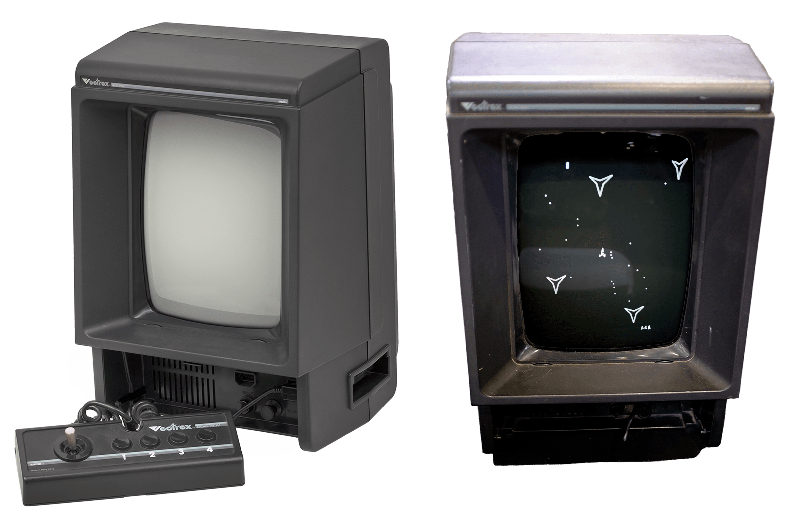
These displays are quite uncommon now but were very practical at the time because you would directly draw the shapes you wanted to show as with a pen, without having to represent the full image in memory. On the other hand, as the beam was moving around the screen it would tend to drift, and longer lines would take more time to draw. Finally, you had to repeatedly draw your shapes as lines on the CRT would fade quickly, and to make sure that your full drawing would take less time than the light decay[3].
Putting aside these limitations, I found it interesting to try and perform wireframe 3D rendering on the Vectrex, as it was a very different way of thinking about image generation. But how do you write and test programs for a fourty years old console which has very limited specifications?
The Vectrex platform
The Vectrex hosts a 1.5MHz 8-bit CPU (the Motorola 6809) that can perform 8/16-bit integer computations, and doesn't support floating point numbers. It is coupled with a 1kB RAM bank (including reserved hardware addresses and stack). The cartridge ROM containing the executable and its data is a 32kB bank. Access to both banks is fast (~3 CPU cycles) and achieved through 16-bit addresses. Two controllers can be connected to the console, each with four buttons and a two-axis joystick.
Fortunately, it is quite easy to setup a Vectrex development toolchain on a modern computer, as described by Johan Van den Brande, thanks to the CMOC C compiler targeting the 6809 processor. The compiler also provides wrappers around Vectrex-specific assembly instructions for device initialization, input handling and vector drawing. Furthermore original documentation and listings can be found online[4].
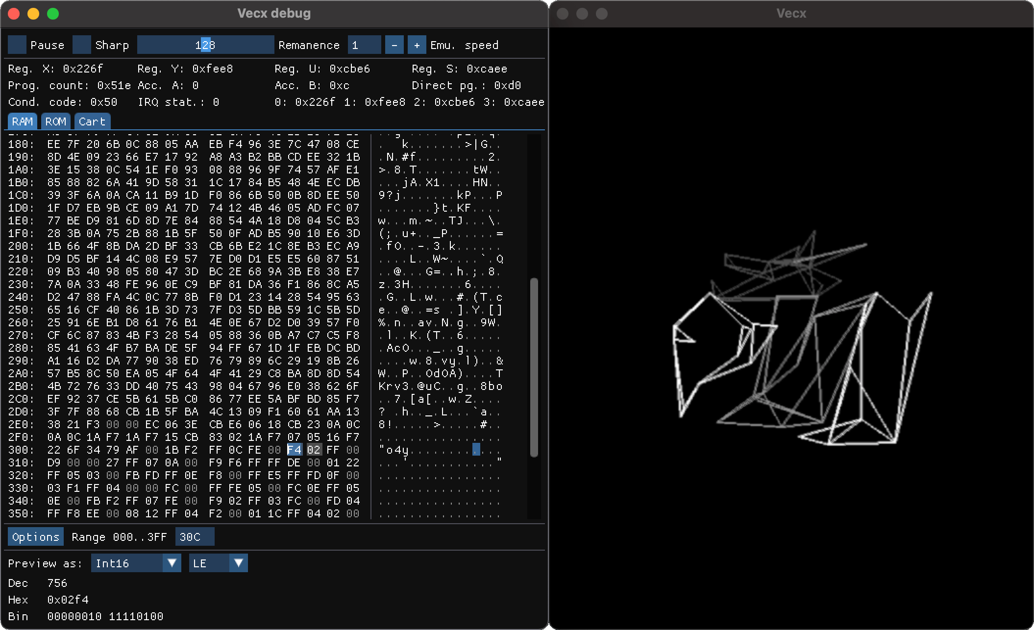
To run Vectrex executables without the real console and writable cartridges, I had to rely on an emulator. I modified a SDL2 version of the Vecx emulator to help me debug my attempts. I used ImGui to add visualization in order to peek at the memory and registers, along with additional controls for the display and a high-performance mode to test ideas before having to optimize anything (fork available here). All results presented below use the standard Vectrex emulation settings (regular clock speed and CRT decay rate).
Rendering attempts
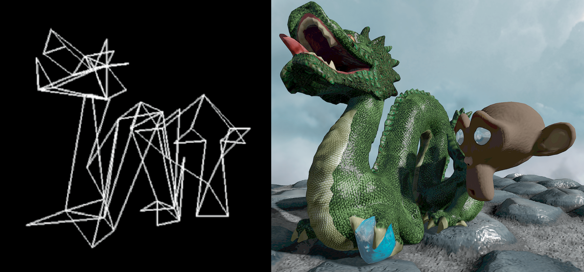
I'm now going to describe my successive attempts at getting a very simplified version of the dragon scene rendered at interactive frame rates. I chose to keep things reasonable: render the dragon and monkey as wireframes, and only allow for a very simple camera zoom and rotation around the objects.
Naive approach
I started from the geometry I had created for the PICO-8 version of the scene, as it was already heavily simplified. The meshes are placed in world space and their coordinates normalized in [-127,127], so that they can be stored on one byte per component. Combined with the triangle vertex indices, the geometry was using less than 1kB of the cartridge space.
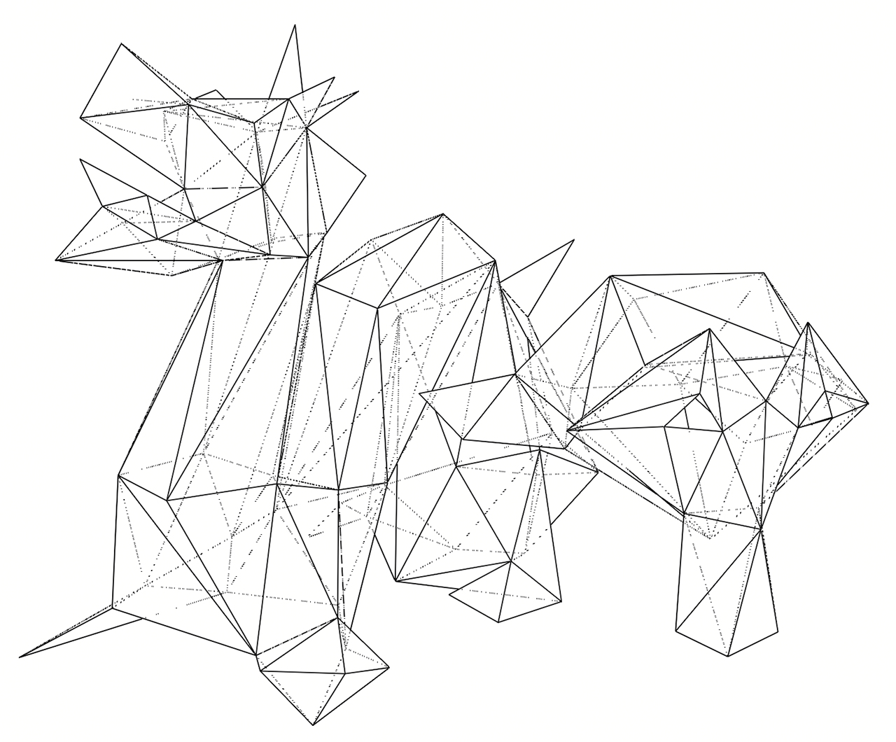
The plan was then the following, for each object:
project the vertices from world space to screen space using a very basic view and projection transformation (rotation around the vertical axis, 90° field of view, no per-object transform) and store the resulting 8-bit 2D coordinates in a temporary buffer on the stack.
for each triangle, emit instructions to draw the three edges based on the screen space coordinates and reset the electron beam
Because there was no floating point support and 32-bit integer operations were slow, I performed all computations on 16-bit integers, ensuring that I was avoiding overflow by manually tracking the value range at each step and performing divisions by carefully chosen constants when needed. The perspective division especially required some tweaking to avoid losing too much precision.
For the camera rotation, I needed trigonometric functions that were not available[5]. I thus relied on precomputed look-up tables for cosine and sine, scaled to maximize precision while avoiding overflow when multiplying them with mesh coordinates. Even for 1024 predefined angles and 16-bit values, it only took 4kB in cartridge storage, which was worth it.
The result was promising, but extremely slow. The computations and drawing were taking so much time that the lines had time to completely disappear before the beam would draw them again...
Refining everything
I started simplifying every possible step:
- I manually shaved 40% of the faces off in Blender, trying to preserve the salient details of the dragon and monkey.
- As each edge was shared by two triangles, it was drawn twice. I moved from lists of triangles to list of edges, even if it meant storing more indices in the cartridge.
- I replaced constant divisions by bit-shifts (the compiler was not always able to do it automagically).
- I stored a second look-up table for the perspective division.
- I split objects in separate vertex and index lists to use 8-bit indices when iterating.
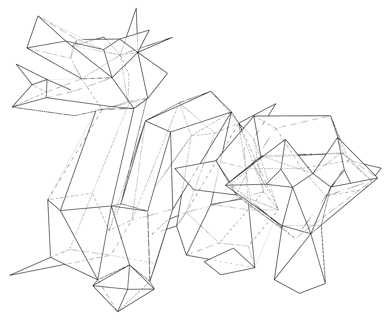
Most importantly, instead of issuing a draw instruction for each edge and moving the beam in-between, I started to create more efficient draw lists. The PACKET and LPACK instructions allow for the submission of a batch of draw/move commands represented as a list of actions and screen coordinates in a list in memory.
Again and again
This was still not satisfying, so I reworked the geometry again, dividing the number of vertices and edges by almost two. I relied more and more on non-planar faces to lower the edge count, which Blender handled quite well. But preserving the important features of both meshes was becoming increasingly difficult.
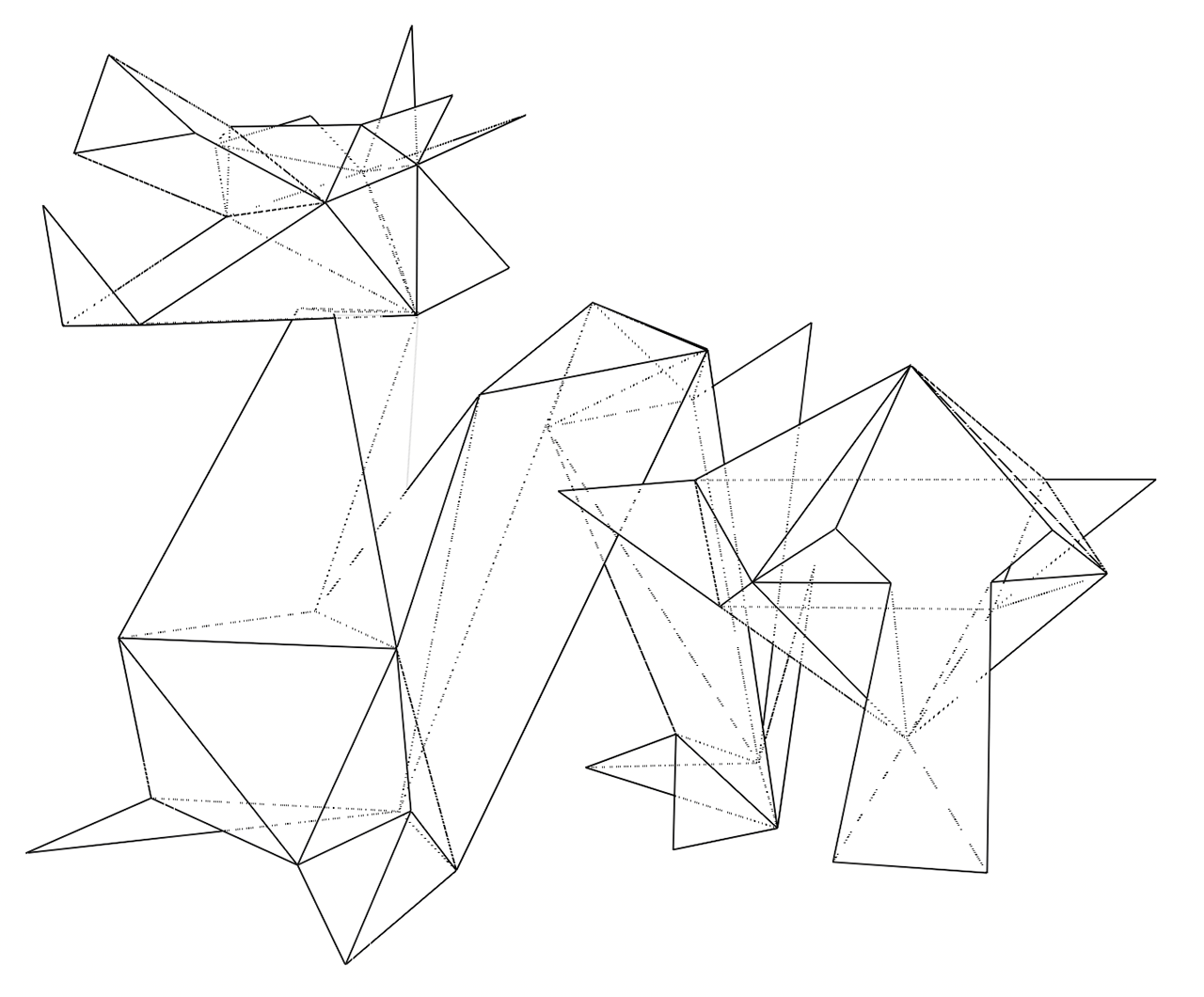
Even with these alterations, projection and drawing were still taking a bit more time than the CRT persistence would allow, at least on the emulator ; on an old CRT it might be easier to get away with it. At this point, I felt a bit stuck: I could try and inspect the dissassembly to optimize the code further, or start reordering edges to minimize beam displacements, but both would require a lot of work for an unguaranteed result.
Bake all the things!
Thinking about the problem again and trying to find ways to minimize the number of computations, I realized that the only varying parameters in the scene were the zoom and the camera rotation around the center of the scene. The zoom can be handled using a global screen scaling parameter exposed by the Vectrex. On the other hand, the rotation is a more complicated issue, as it has to be applied on the world space vertices and requires a look-up table and multiple mathematical operations.
But we currently have more than 20kB of cartridge storage unused. What if, for a wide range of rotation angles, we performed all transformations as a preprocess and stored the resulting screen space coordinates in the cartridge? For 64 vertices, if we divide the circle in 128 angles we need approximately 16kB to store all the 2D coordinates. A small preprocessing tool is used to dump all the precomputed vertex positions ; we can simply then retrieve them at runtime based on the current camera angle.
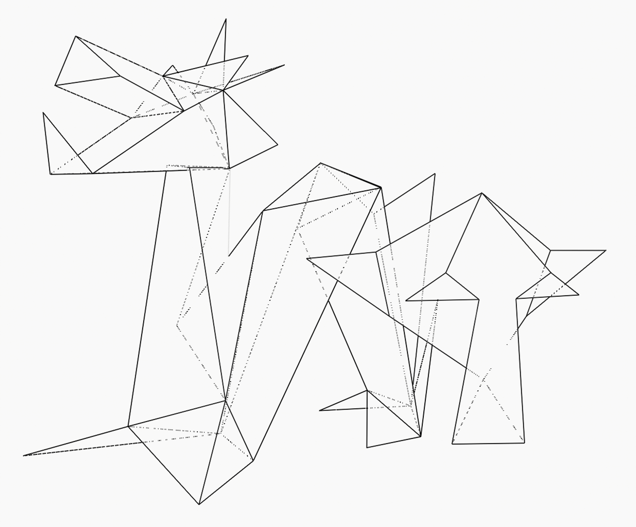
I also removed a few extra edges along the way, which did not hurt. With all of this, I finally managed to get an almost stable display the user can interact with. The performance is now bound by memory access and the draw list execution. At large zoom levels the display still flickers a bit too much because the beam has longer distances to cover, but I was overall satisfied with the result.
Conclusion
As with previous versions of the Here be Dragons project, it was a very fun and interesting challenge to try and fit my target scene on such a constrained platform. This was the first time I had been confronted to a complete lack of floating point support, which was a strong reminder of how far we have gone when it comes to computing power and amenities on modern hardware.
I am sure extra performances could be gained by moving from C to writing Vectrex assembly directly, especially as the logic of this demo is much simpler than an interactive game. But I am already happy with the current result, even if in the end it amounts to a glorified video playback[6].
The final source code, resources and preprocessing tool are available in the Here be Dragons repository.
-
Which excites phosphors on the surface of the screen and cause them to subsequently emit light when returning to their base energy level. ↩
-
Credits: left: Vectrex Console Set by Evan-Amos, CC BY-SA 3.0, right: Vectrex Asteroids by leighklotz, CC BY 2.0, edited for contrast. ↩
-
As we will see later on, this will be the root of my issues. ↩
-
The page is in french but the PDFs are in english. ↩
-
There are sine/cosine instructions available but only for 8-bit precision and with strongly discretized angles. ↩
-
Incidentally, vectorization-based approaches to video compression have been explored in the scientific litterature. ↩