Running another Experience 112
Table of Contents
In a previous post, I have explored how the game eXperience 112 stores its resources, describes its levels, and renders frames. Rich with this information, I wanted to attempt to display the game levels in a custom renderer. Hopefully we should now have enough insights to get pretty close to in-game renders. But rather than re-implementing the exact same rendering approach as the game, we will use techniques that were not available at the time of release. If you are here for a more detailed overview of the game levels, I promise that another post should follow up shortly, hang in there.
Loading a level
As described in my post analyzing the game data, we have to parse DFF and AREA files to collect 3D models, WORLD files to build the levels. We also need to load various image formats for the textures (PNG, TGA, DDS,...).
DFF is a binary format used by some popular games from the 2000s, so parsing details are easily found online. The format allows for extensions that are also well documented, the only one interesting here being the specification of an additional normal map texture. With a bit of additional investigation in an hexadecimal file viewer [1], I was able to write a decent parser that extracts geometry and materials. The only thing I belatedly realized is that materials with a transparent base color are meant to be treated as, well, alpha blended instead of opaque.
The other formats are XML-based, and are parsed using pugixml. The main challenge then consists of mapping the text-based attributes to intepretable data. Most parameters for lights, cameras and entities were self-documenting, but a few required experimentations to check if my assumptions were correct. Observing how assets are rendered in the final game using the same frame inspector I mentioned in my previous post, was very efficient in that regard. I was for instance able to determine how the geometry for particles and billboards[2] should be generated, and how they should be blended with their surroundings. For lights, this clarified how their area of effect is defined depending on their type, and how spot lights with a null opening angle should be treated as omnidirectional point lights.
The most complicated case I've encountered was the interpretation of the parameters specifying the in-game cameras orientation, which were expressed as two constrained angles in a local frame. I had to disassemble the game binary using Ghidra to finally understand how to turn them into regular transformations and place the cameras in the level.
Texture loading was comparatively very simple. Non-compressed images are loaded with stb_image. I am relying on another library, dds-ktx, to parse DDS files which can contain multiple mip levels, cubemaps faces or other multi-image textures. The compressed formats used in these files are fortunately still supported by modern drivers.
Rendering a level
The original game was rendering each object multiple times, to accumulate contributions from the ambient environment and the different light sources. Object visibility was determined on the CPU with the help of occlusion queries. Shadows were using a popular technique at the time, shadow volumes[3], generated on the CPU for static objects.
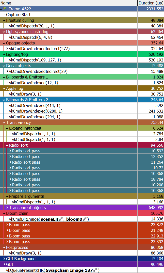
Instead, we will try to do as many things as possible on the GPU. We will determine visible objects by frustum culling them in a shader, outputing lists of indirect draw calls. These calls will be directly executed to fill a G-buffer[4] containing parameters for the visible surfaces. Meanwhile, another shader will detect which lights are covering the visible field of view. The result will be used to perform clustered lighting on surfaces stored in the G-buffer, all at once. Fog zones will be clustered and applied in the same way. Shadows will rely on good old regular shadow maps. Particle effects will be generated at loading and rendered in a minimal number of draw calls. Transparent objects will be rendered at the end, while fetching in the same data structures for lighting and fog. To ensure they are properly blended together, we will implement a radix sort to order them back to front in a shader. Finally, we'll re-implement the post-processing stack.
To simplify things, we are going to assume that everything in the level is static. We won't tackle animated meshes, lights nor effects for now. It ensues that we can prepare the data and send it to the GPU all at once during level loading. Any rendering step will then be able to access all the level data and information without any extra work. This is called a bindless approach, because we don't have to bind specific resources to any given shader.
Let's implement this
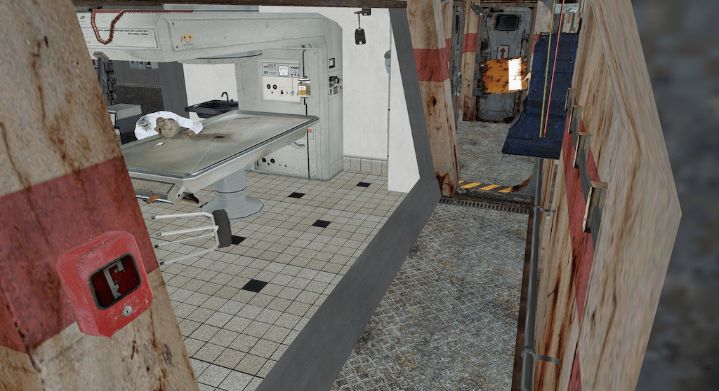
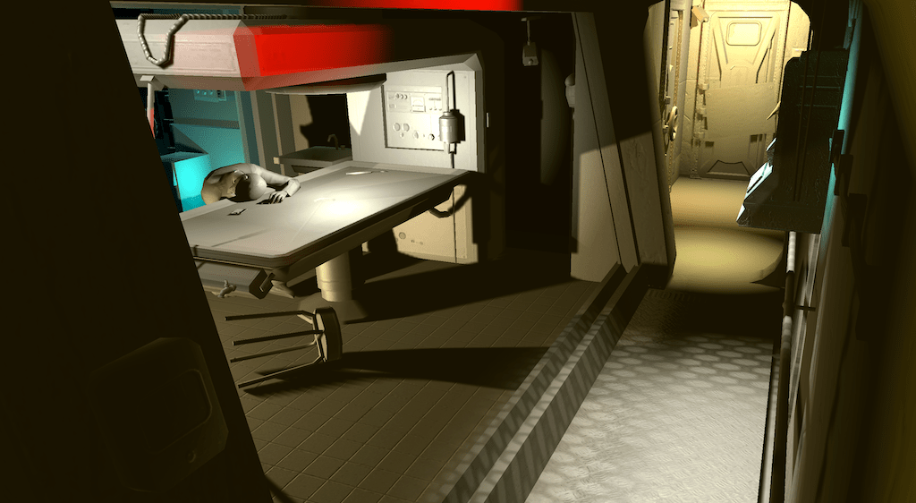
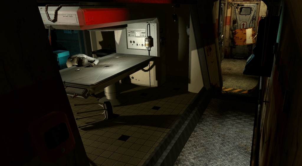
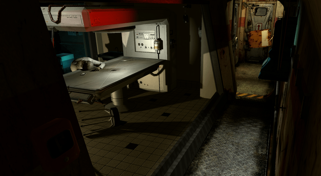
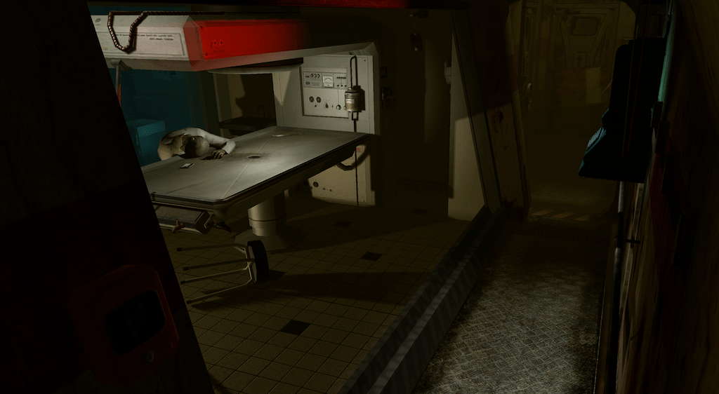
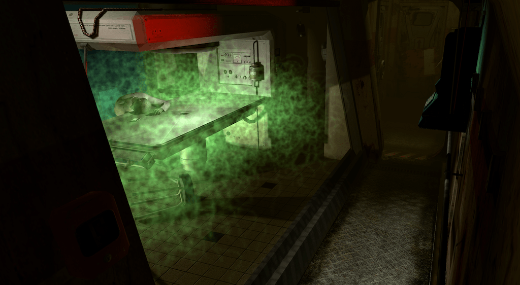
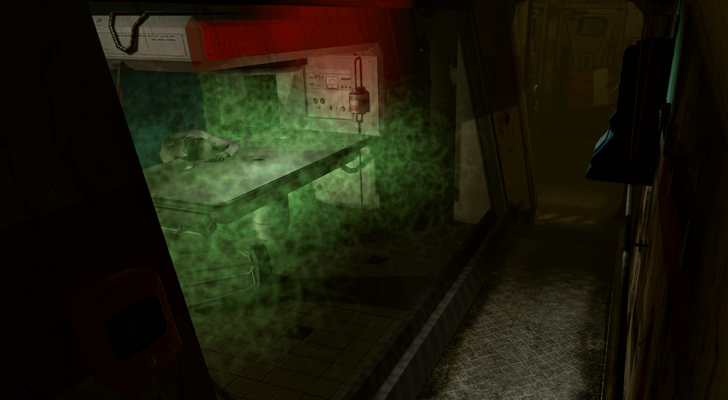
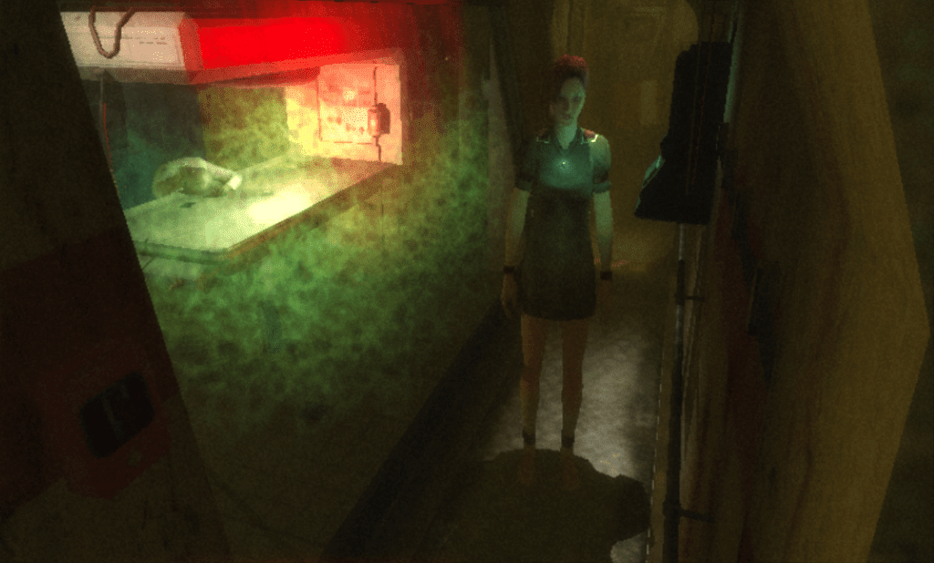
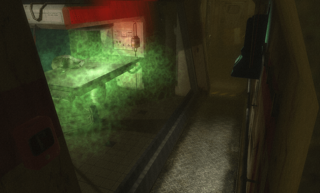
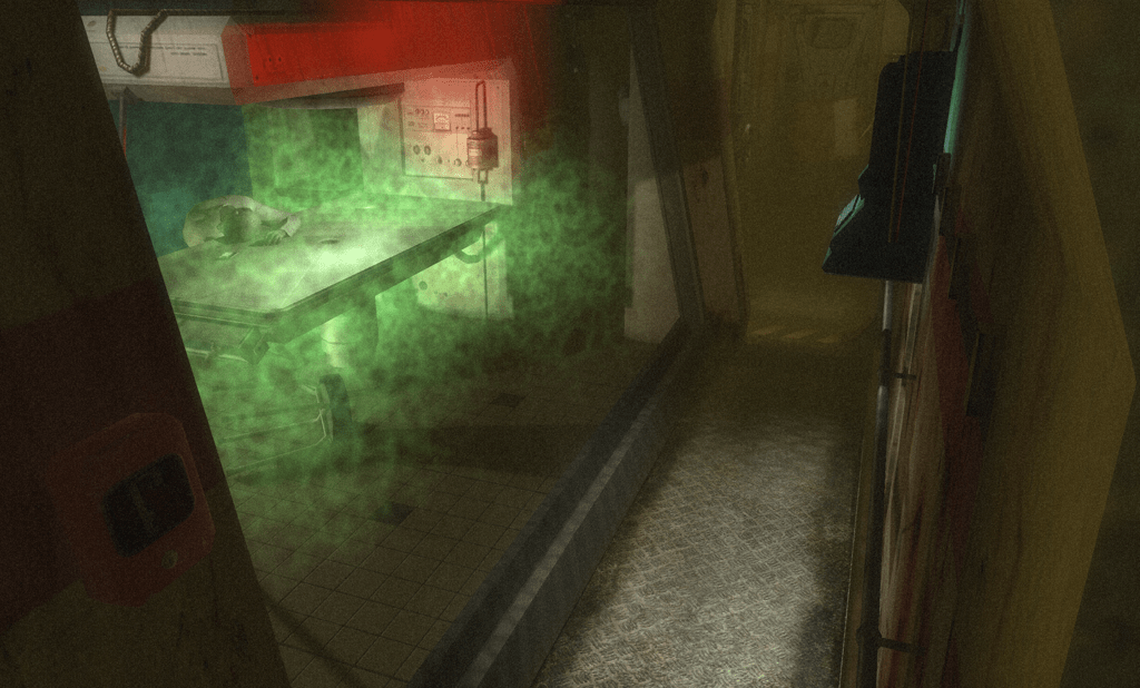
The renderer is implemented in Vulkan, and is based on the same foundation as my playground rendering engine Rendu. The core engine papers over some of Vulkan most gritty details, such as handling resource allocation (with the help of the Vulkan Memory Allocator), data transfers and synchronization, pipeline state caching, shader reflection (using SPIRV-Cross), descriptor set layouts and allocations, and swapchain management. The graphical user interface is built with the great Dear ImGui library. As in the first post, we will focus on this view from the UD05b-04 camera in the tuto_eco.world level:
Expect other random bits of Vulkan details at some points below.
Bindless data
We will be sending most of the scene information to the GPU, packed in multiple storage buffers in an efficient manner:
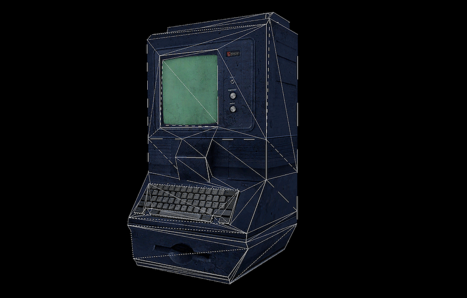
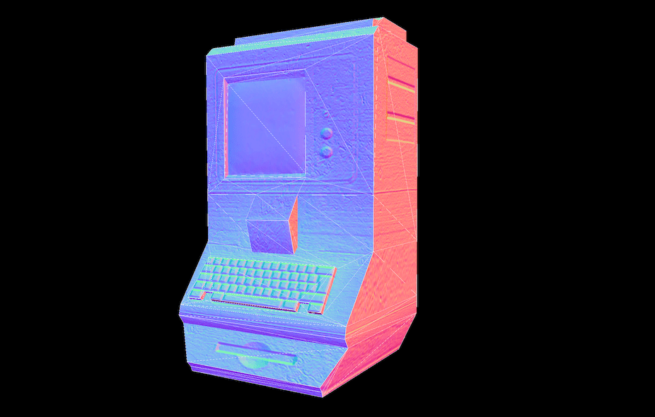
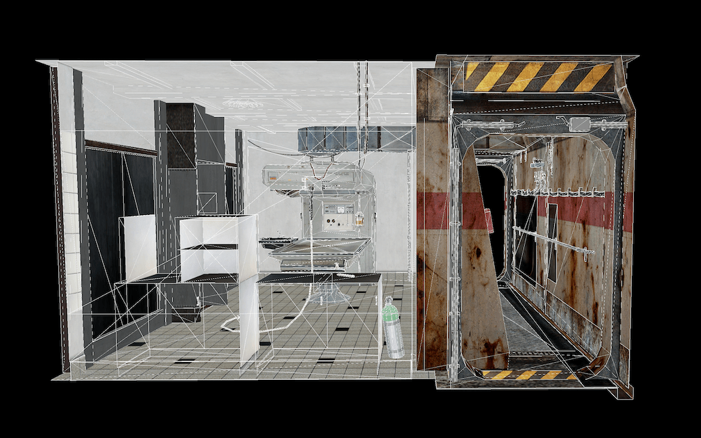
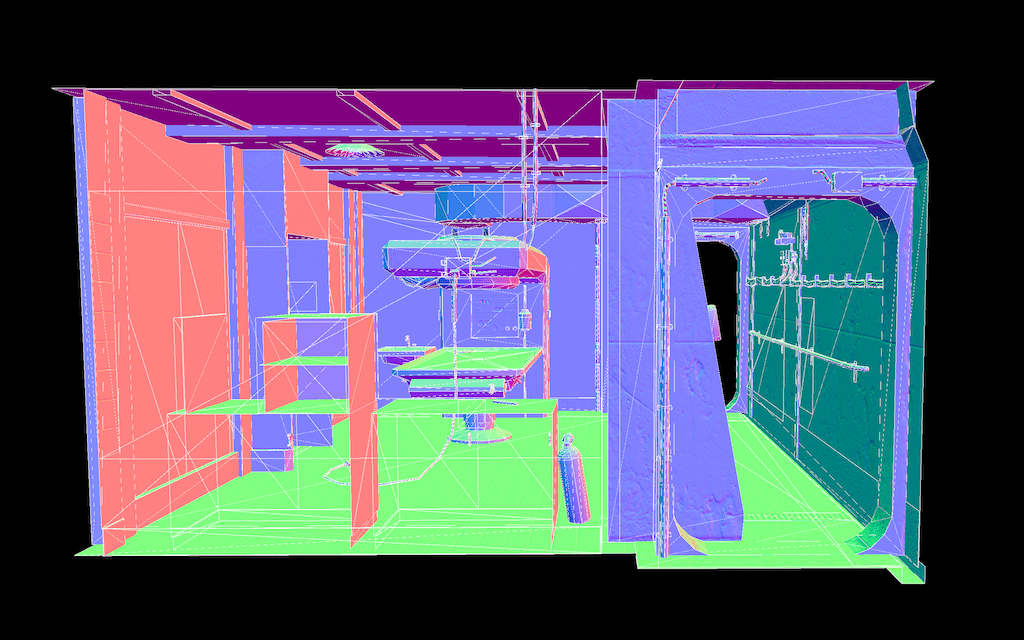
- The geometry of all opaque, transparent and decal objects is regrouped in a unique pair of vertex and index buffers. This contains positions, texture coordinates, colors if they exist, normals, tangents and bitangents, and triangle indices.
- A second mesh is built to store the particles and billboards, grouped by type.
- A buffer stores the list of all materials, each providing a base color, and indices to diffuse and normal textures.
- Another buffer stores each mesh information, including their bounding box, the index of the material they use, their vertex and index ranges in the global geometry buffer, and the range of instances that use this mesh.
- A larger buffer will list the transformation matrix of each instance.
Assuming everything is static, none of these buffers have to be updated while moving around the level. A separate small buffer containing frame data (camera pose, frame time, settings) is updated and sent to the GPU each frame.
Textures are regrouped by dimensions and pixel format, and packed in texture arrays. Each such array is represented by a descriptor (a pseudo-pointer visible from shaders) ; all array descriptors are then collated in an unbounded list exposed to all shaders[5].
In Vulkan, this requires the
VK_EXT_descriptor_indexingfeature to be enabled, fortunately available in Core since 1.2[6]. This allows us to create descriptor sets with a variable size (VK_DESCRIPTOR_BINDING_VARIABLE_DESCRIPTOR_COUNT_BIT_EXT) and to update them while some sections are being used (VK_DESCRIPTOR_BINDING_UPDATE_AFTER_BIND_BIT_EXT,VK_DESCRIPTOR_BINDING_PARTIALLY_BOUND_BIT_EXT). In the shader, a set is reserved for an unsized array of textures:layout(set = 3, binding = 0) uniform texture2DArray textures[];. We might also enable theshaderSampledImageArrayDynamicIndexingflag if some synchrnous shader invocations might access different textures, which the shader needs to be aware of.
A bindless representation introduces additional indirections when fetching information on the GPU, but requires much less work on the CPU. To illustrate: when drawing an object, one would usually have to tell the shader which parameters and textures are required through CPU calls and indexed resource slots. Instead, the shader will identify which instance of which mesh is being rendered thanks to an index provided by the hardware. This will be used to subsequently load object information, pointing to some material information, which will itself provide texture indices. With these the shader will be able to index in the large array regrouping all textures.
Frustum culling and indirect draws
Before rendering anything in the frame, we first determine which instances of which objects are visible on screen, in the frustum of the camera. This helps minimize the time spent rendering objects that won't be visible in the final image. Instead of spending time performing this on the CPU, we use a compute shader. Each dispatched thread processes a subset of instances, testing their bounding boxes against the frustum planes. The shader then populates indirect draw call information, as small struct for each mesh, providing the following information: the range of triangles to render, and how many instances should be rendered.
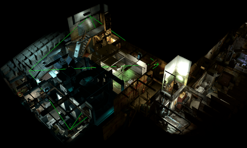
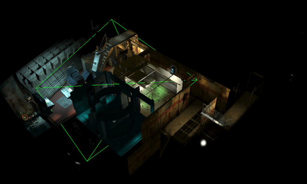
The advantage of using indirect draw calls is that all objects will then be rendered in a unique CPU draw call, once again minimizing the time spent in the driver. Each draw argument in the list points to a different region of the global mesh, and the hardware will feed to the shaders an index for the argument (corresponding for us to the object mesh index), and an index for the instance.
This requires us to enable the
multiDrawIndirectfeature, and to usevkCmdDrawIndexedIndirectcalls to submit our draws, providing an argument buffer created with usage flagVK_BUFFER_USAGE_INDIRECT_BUFFER_BIT. We also need to enable theVK_KHR_shader_draw_parametersextension to ensure shaders receive agl_DrawIDalong with the always availablegl_InstanceID[7].
Opaque objects
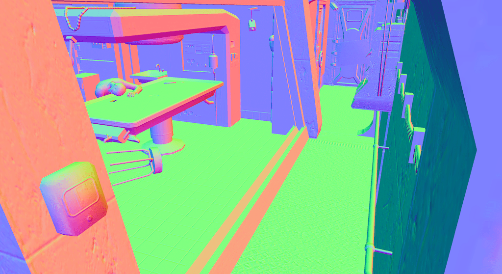
All opaque objects are rendered at once, using the same shader. As already explained, each instance retrieves from the global buffers its transformation, its mesh information and its material, including texture indices. The fragment shader then samples these textures to evaluate the instance appearance, but we do not perform lighting yet. Instead, color, normal and shininess are output to a G-buffer, a collection of textures that will store these parameters for the foremost visible surface at each pixel. The G-buffer will then be loaded when applying lighting and fog. The goal of this approach is to decouple the cost of rendering objects and evaluating the lighting ; we avoid shading surfaces that would later be hidden by another object in front of them.
Clustered lighting and fog
Similarly to what we did for objects, we now determine which lights are visible in the field of view. But instead of building a list of lights for the whole frustum, we slice it regularly along the three axes, creating frustum-shape voxels (froxels). In a compute shader, each light bounding sphere is intersected against each froxel bounding box. We also test the visibility of ambient fog zones, which are represented as axis aligned bounding boxes in world space. This gives us clusters of lights and zones for each froxel.
Observing the game levels, we never encounter more than 128 lights per scene. As a consequence we can use a bit field to mark which lights are contributing for a given froxel. This 128 bits value is stored in the four channels of a RGBA32 3D texture, each texel being mapped to a froxel. For fog zones, we limit ourselves to 16 zones per scene.
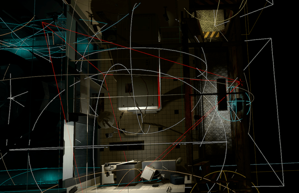
Then for each pixel of the G-Buffer, we can compute its position in world space, and determine the froxel it falls into. We retrieve the bit field from the 3D texture and iterate over the active lights in the cluster. For each of them, we evaluate their diffuse and specular contribution using the same Lambertian and Phong models as the original shaders. Lights can cast shadows, in which case we reproject the current pixel in the corresponding shadow map and check if it is visible from the light viewpoint. If the light is a projector, it also has a material and we sample the corresponding bindless texture to modulate the lighting color.
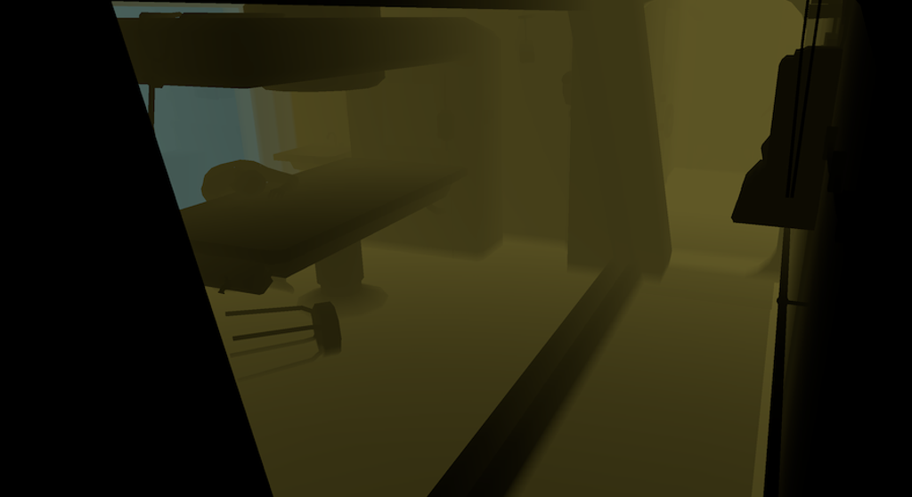
As we have already determined in which froxel a given pixel falls, we also retrieve the fog zones in the cluster, and evaluate the global fog color and transmission. A small blending is applied at the edges between zones to ensure smooth transitions. The result is stored in a separate texture because it will be applied later, on top of decals and some of the particles.
Shadow rendering
Because we assumed everything is static, shadows are rendered progressively upon level loading and then reused at each frame. Each shadow casting light is assigned up to six layers in a shadow map array, depending on whether it is an omnidirectional light or not. We assume that only opaque objects are shadow casting.

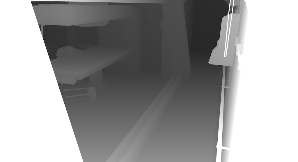
When requested, a shadow map is rendered by performing a separate pass of frustum culling and indirect draw, this time using the viewpoint of the light. For omnidirectional lights, we shoot the six faces of a cube, as shown above. We generate one shadow map that way each frame after loading, until all the lights have their shadow maps.
Decals
Decals are objects that apply a color on top of whatever object lies below them on screen. They are usually very simple geometry overlaid just above another object to add dust, rust or similar effects. In eXperience 112, they do not receive lighting but are covered by fog (which explains why they are rendered at this point). In our renderer, they have been culled at the same time as opaque objects, and consist of a unique indirect draw call.
Particles and billboards
Particles and billboards are rendered in their own pass for two reasons:
- they use various blending modes: additive for sparks, screens and LEDs, multiplicative for dirt and splatters, alpha blended for smoke, etc. Blending state cannot be changed in the middle of an indirect draw.
- the level does not provide geometry data for them, only sets of parameters for their generation and simulation at each frame. They will need a dedicated shader.
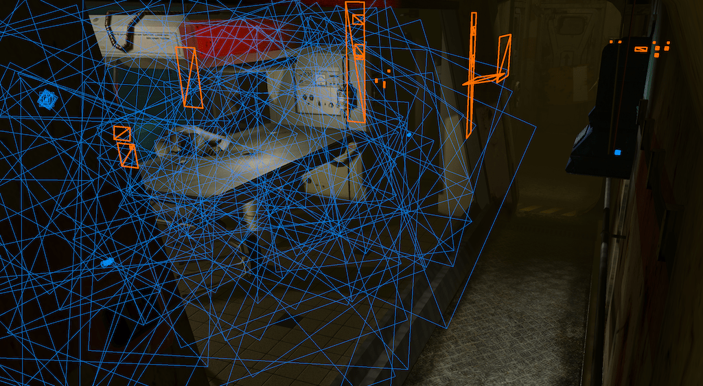
Because we want everything to remain static, we emulate a simulation step at load time, and then upload the resulting mesh once and for all. Billboards are the simple case, as they are always composed of one quad with a specified size and a standard transformation. A vertex attribute is used to flag whether the quad should remain in world space or should turn to always face the viewer (on one or all axes depending on some setting).
Particles on the other hand are more complex to recreate, as they can have additional simulation parameters and forces applied to them in configuration files. I've only implemented a basic version that respects the boundaries of the area they should spawn in, their color variations, and the general direction and speed of emission.
In the end, everything is sorted based on the required blending modes and concatenated in the same mesh. We end up with a few consecutive draw calls, each rasterizing a different range of primitives in the mesh. The shader will orient the quads based on their attributes and apply the proper material. Some particles should be rendered before the fog, other afterwards. Thus the fog result texture from a previous step is composited inbetween some of the particle draw calls.
Transparent objets
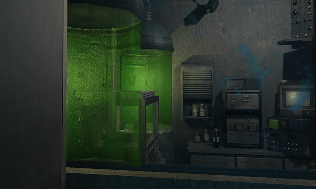
Lastly, but certainly not least in terms of the required work, transparent objects need to be rendered with alpha blending. Such blending is non-commutative, meaning that if objects are rendered in the wrong order artifacts will be visible, as in the figure below. We thus have to ensure that all such surfaces are rendered back-to-front. The original game was sorting objects on the CPU and drawing them one by one, but we would rather do this on the GPU, by reordering our indirect draw arguments generated after frustum culling.
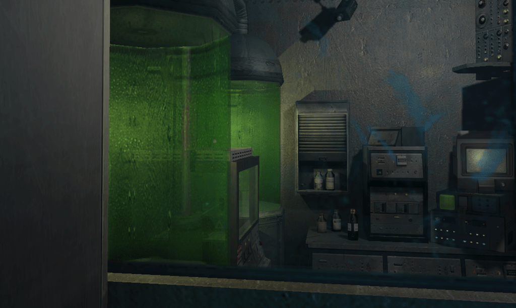
We start by filling a buffer with information for each visible instance of a transparent object ; namely its mesh index, its instance index and the distance from the center of its bounding box to the camera. We then perform a radix sort, using the computed distance in centimeters as an integer key.
This sort maps quite well to the GPU, the idea being to bin items based on their key. If we were to do this naively, we would need as many bins as we have keys. Instead we run multiple sorting passes, each looking at four consecutive bits of the key. At each iteration, we'll thus put our items in sixteen bins. As a first step, we count how many items are falling in each bin, by having a shader atomically increment sixteen counters as it iterates over items. These counters can be merged to compute bin offsets, and a final shader copies our items into a new list, using the offsets to put them in the proper bin. Because this technique is a stable sort, sorting from the least to the most significant bit ranges ends up sorting the list globally. One last shader converts back our items to a list of indirect draw arguments, each rendering a unique instance.
A multi draw indirect call then goes over this sorted list of commands, rendering each instance with the same shader with alpha blending enabled. The shader performs both material evaluation and lighting/fog computations, using the same shared structures as the main lighting pass.
The sort is done in multiple rounds, each using three compute shaders. The first one performs the count, with one thread per instance performing an
atomicAddto one of 16 integers in a buffer flaggedcoherent. The second shader is dispatching a lone thread to perform a prefix sum on the counters to convert them to offsets. The last shader runs a thread per item again and appends items in the proper bins, incrementing the corresponding offsets along the way to ensure no overwrite.
A smarter version could rely on local data share and theGL_KHR_shader_subgroupfeatures to minimize contention on the atomic counters. It would firstly mutualize computations for each wavefront usingsubgrouparithmetic operations, gather results in a localsharedset of counters and finally pick a thread withsubgroupElect()to increment all global atomics. In that case, we might want each thread to work over multiple items at once to benefit even more from the grouping.
Postprocess stack
The few last steps of the frame apply post-processing effects. Most effects are optional and apply depending on the in-game cameras state or based on user interactions. The original game implemented this with a set of fullscreen shaders, which can be ported almost as-is. There is not a lot a modern approach can change here, except merging most effects in a unique compute shader.
Bloom
Similarly to the original game, a copy of the current view is downscaled and blurred multiple times before being accumulated and re-composited on top.
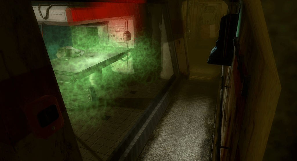
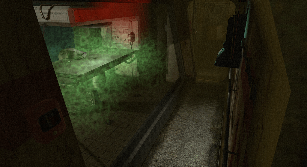
Grain noise
A simple noise texture is applied on top of the scene with a random offset each frame.
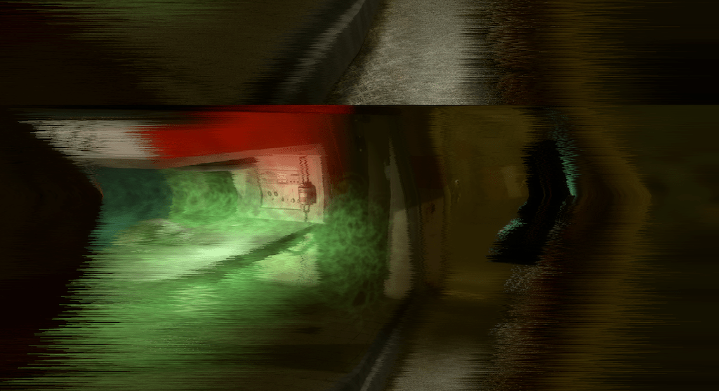
Jitter
The image is distorted heavily using animated random noise in a way that mimics a faulty CCTV quite well.
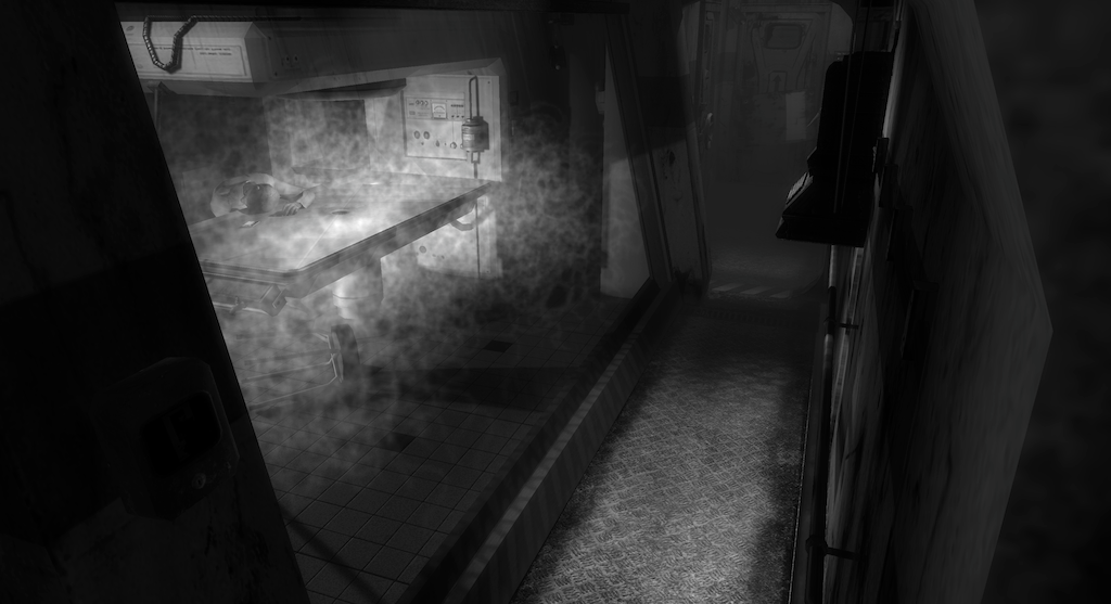
Black and white
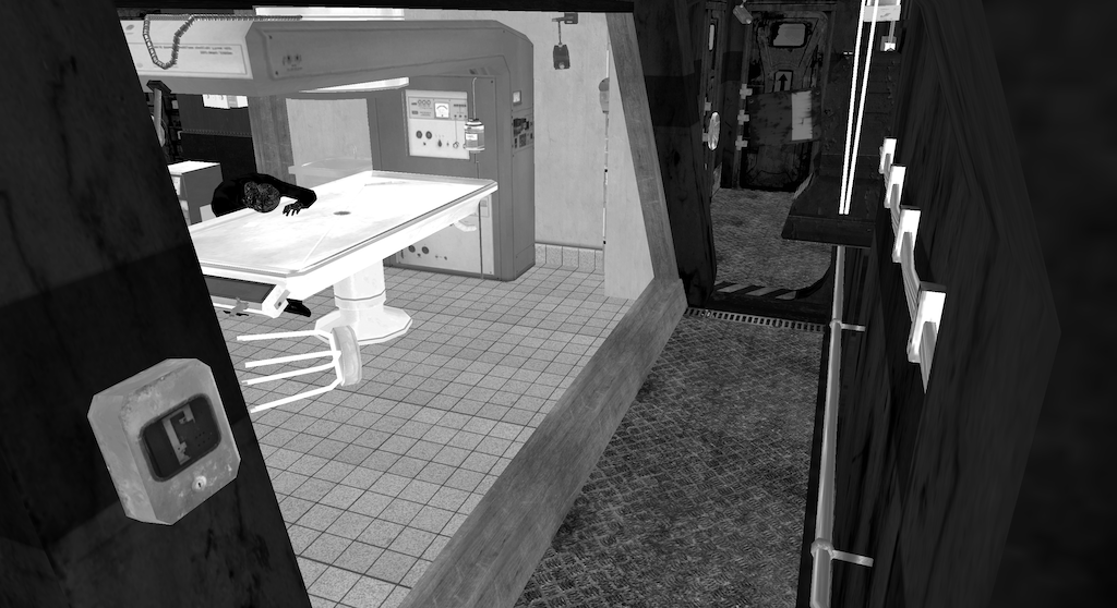
This effect just outputs the luminance of the render.
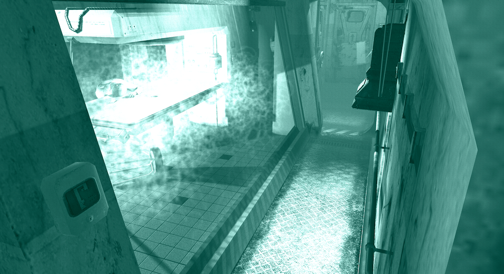
Underwater
A blue tint is applied and the image is distorted with a low frequency animated noise, as if water was moving in front of the camera.
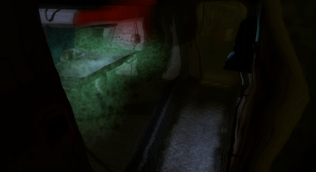
Night vision
This one also relies on grain noise, combined with temporal variations in luminance and a greenish tint, to mimic infrared cameras.
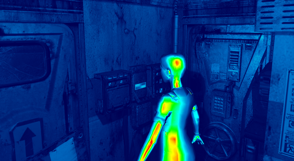
Heat
The last effect is more involved: it mimics a thermal camera with a fake colors spectrum. Each opaque instance in the level is assigned a heat value between 0 and 1, representing its temperature. They are written in a separate texture at the same time as the rest of the G-buffer. An additional modulation is applied based on the surface orientation, to mimic a hotter core and colder edges. In the post-processing shader, these values are mapped to a colored gradient from blue to red, composited on top of the rendering.
Conclusion
This second part of the project overlapped with the first part a lot in practice, but the prospect of exploring the levels was a huge motivation throughout. Mixing old game data and recent rendering techniques is obviously solving a non-problem in the first place. But the game data being a known quantity gave me more leeway while implementing a first version of the renderer. This was a good way to get acquainted with techniques such as clustered lighting, indirect draw calls, GPU sorting, etc. In the end, the renderer can inspect levels, areas, models, textures, and display information on lights, zones, particles/billboards, cameras ; the code is available online.
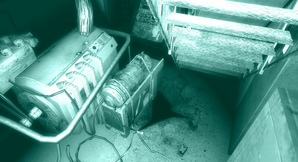
The nice thing with this kind of project is that it is always possible to add further improvement later on. When I recently resurrected the code for the previous write-up, most of the data parsing and basic rendering was complete, but other features were absent: omnidirectional shadow maps, ordering of transparent objects, particles and billboard, fog zones clustering, are all features I have added in the last two months.
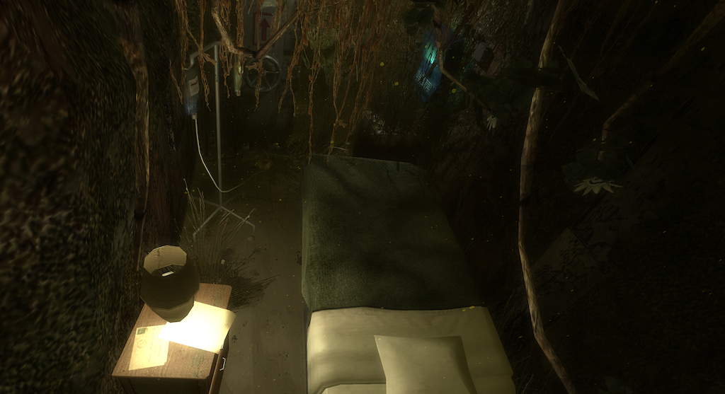
The following limitations could be interesting to push further:
- The big one is the assumption that everything is static. This means that there is no animation nor simulation support right now, and things such as the shadow map shoot and geometry upload would have to be reworked.
- Similarly, no support for interactive events. Some lights and effects are forcefully enabled in the renderer while they should in reality be triggered by gameplay scripts.
- Regarding accuracy : selection of lights and zones was originally done per object, not per pixel. Here we are more accurate than the game, but that's not necessarily the goal.
- Transparent objects and particles are not always well sorted together, they should ideally be all processed at the same time.
- Shadow maps are a standard but notoriously artefact-y approach; it is harder to obtain sharp shadows everywhere than with the shadow volumes. Porting that to shaders is probably a pain though.
- Particle generation is very basic right now, and does not replicate the complex behaviors simulated in the game.
On the more technical side of things, some compute shaders could be optimized using subgroup operations and local shared data, to minimize bandwidth consumption and contention. Similarly, the blur downscale could be rewritten as a singe-pass downscaling shader.
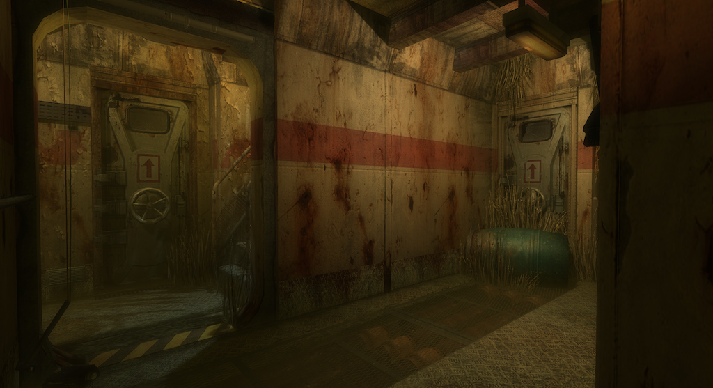
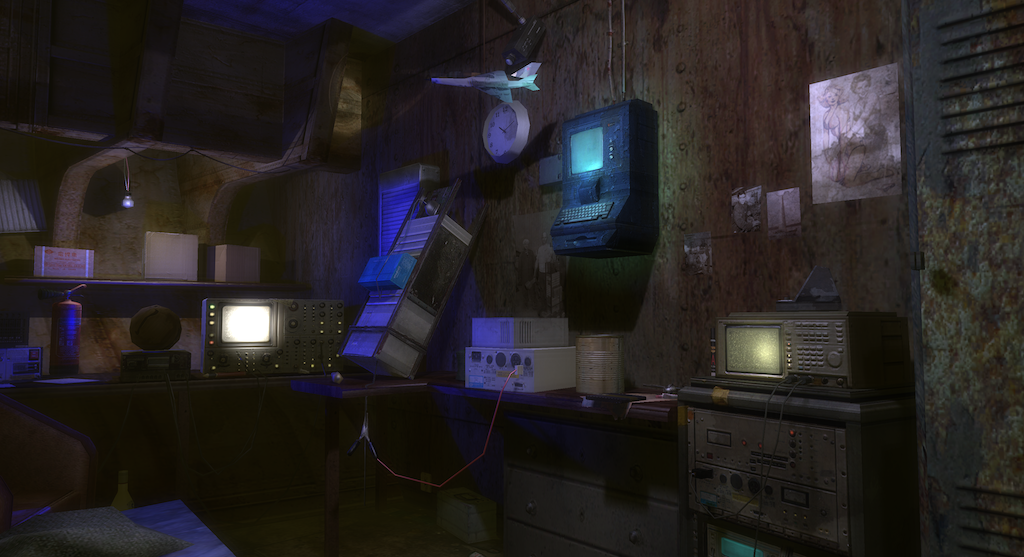
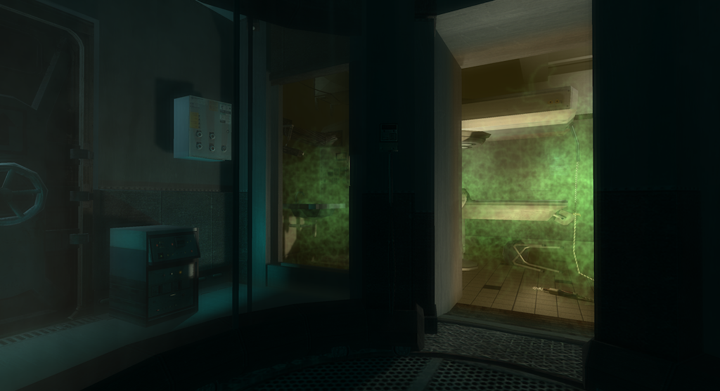
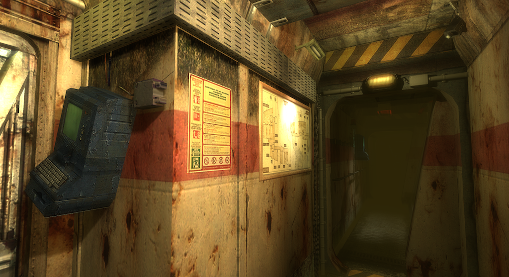
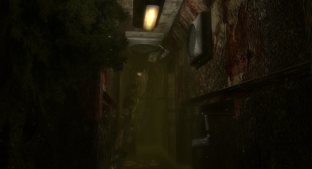
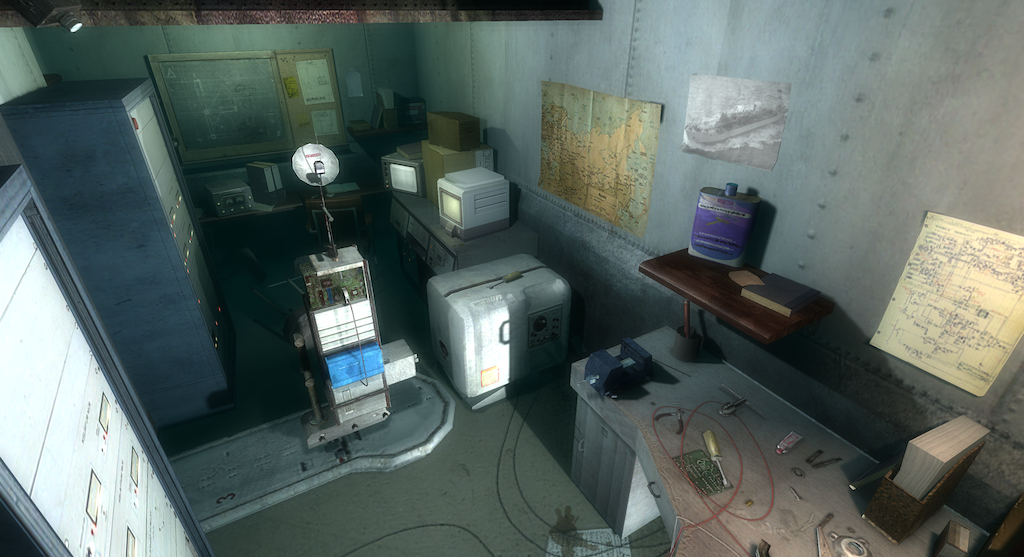
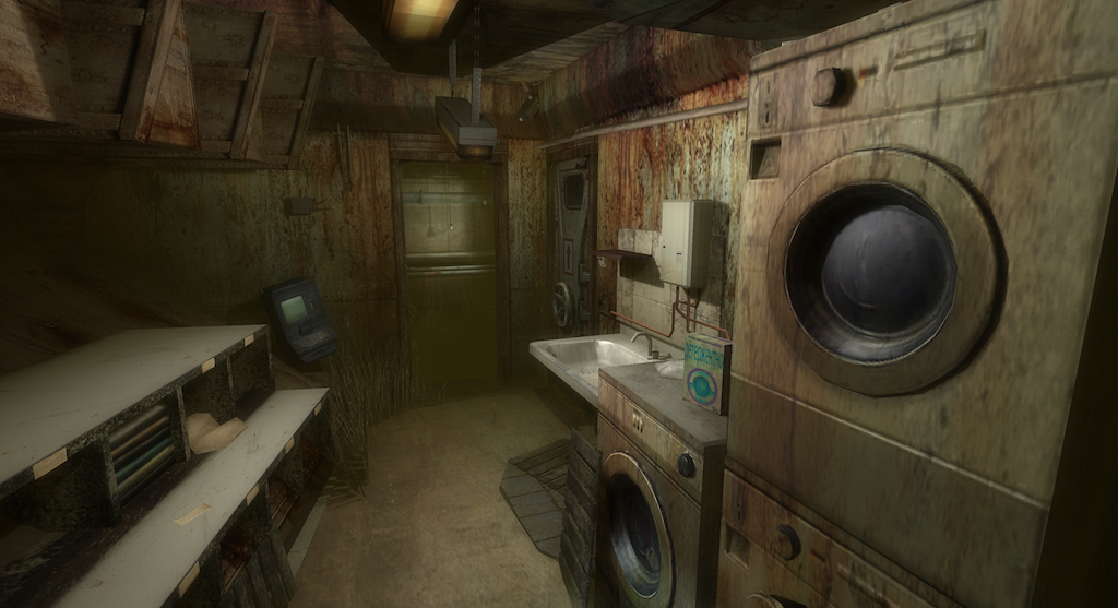
If you've reached the end of this post, congratulations! By now you might be a bit tired of always seeing the same viewpoint in the tutorial level, so here are a few other renders. A follow-up post will provide a more exhaustive overview of the game levels, stay tuned!
-
The interactive file layout description language in HexFiend has been particularly useful for this task. ↩
-
A billboard is a rectangle carrying a texture, usually transformed to either cover another surface in the level, or to always point towards the viewer. They are often used for distant objects or for particle effects such as smoke. ↩
-
See the previous post 'Shadow rendering' section for a basic explanation of this technique. ↩
-
A G-buffer is a set of textures rendered from the viewpoint of the camera, used to store the color, normal, and position of all visible surfaces, along with any other material information needed. ↩
-
Overall we create around 70 texture 2D arrays with resolutions ranging from 4x4 to 1024x1024, using RGBA8, BC1, BC2 and BC3 formats. ↩
-
The grouping in arrays should be unnecessary if the texture descriptor set could be of a really unbounded size, but the minimal guaranteed number of descriptors in bindless heaps is limited on some platforms. ↩
-
Here again, some platforms suffer from limitations and are unable to provide the draw ID. In that case we can mimic the feature by submitting a draw call for each draw argument separately (still using instancing though) and providing the draw ID using push constants. ↩
